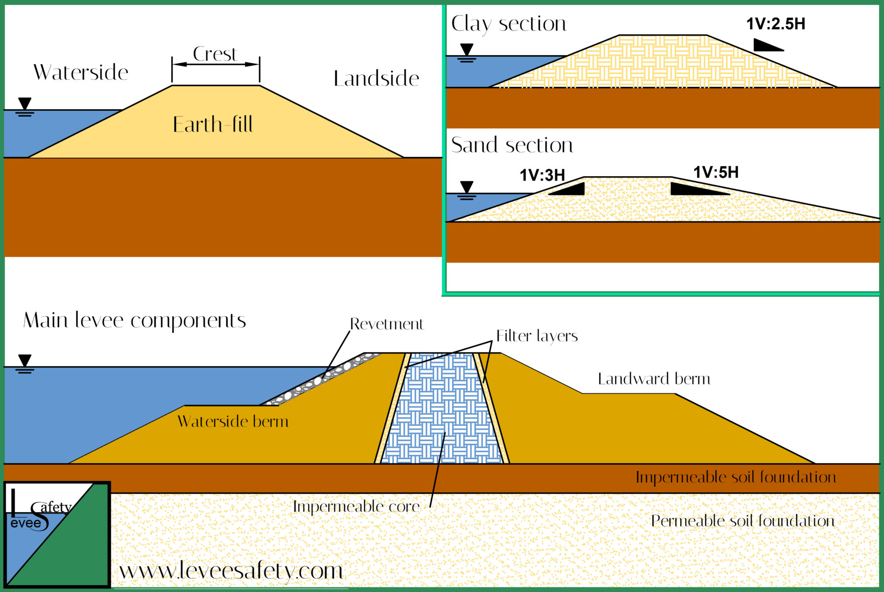
Levee geometry
Levee geometry depends on the levee type; loads; earth-fill material; foundation; height; space limitations (availability of land).
Basically, levees have a waterside and a landside slope and a crest.
The levee should be high enough to provide the required protection level plus an additional freeboard allowance. A levee is generally designed for a particular estimated return period water level. The freeboard is an additional height allowance used in the design of levees to compensate variables inherent in that design (it is a safety factor).
The configuration of the levee is generally dictated by the foundation soils and the materials available for construction.
A 1V on 2H slope is generally accepted as the steepest slope that can easily be constructed and ensure stability of any rip-rap layers while a 1V on 3H slope is the steepest slope that can be conveniently traversed with conventional mowing equipment and walked on during inspections. For sand levees, a 1V on 5H landside slope is considered flat enough to prevent damage from seepage exiting on the landside slope (EM 1110-2-1913).
If foundations have adequate strength, steepness of levee slopes from the stability aspect is governed by the types of compaction, water content control and fill materials.
The levee crest, or crown, provides:
- protection against external agents. Typically, the crest is covered with grass, gravel or asphalt.
- access requirements: maintenance access and roadway. The width of the levee crown depends primarily on constructability and access requirements and future emergency needs. To provide access for normal maintenance operations and flood-fighting operations, minimum widths of 3 meters are commonly used (with wider turnaround areas at specified intervals) which are the minimum feasible for construction using modern heavy earthmoving equipment (a 3 m wide levee crest is needed to safely accommodate a vehicle).
Foundation soils
Foundation soils have to be considered when analysing existing levees or designing new levees.
They bear the weight of the levee and must provide a stable support for it and impermeability and filtration functions.
Levee deposit thickness generally extends up to 10 m. There is wide variability in texture of levee deposits, ranging from clay to coarse sand.
Accurate investigations of the properties of the foundation soils and of the levee materials are required. Geotechnical and hydraulic parameters of soils are the main input parameters for levee design and must be determined through field investigations and laboratory tests.
Levees located on weak foundation soils that cannot support the embankment because of inadequate shear strength such as very soft clays, sensitive clays, loose sands and natural organic deposits require foundation treatments.
Earth-fill
The simplest levee type is the homogeneous earth-fill levee.
Earth-fill levees are only made of soil material.
The main function of the earth-fill is providing mass stability against water pressure and minimizing through-seepage.
Earth-fill provides both stability and impermeability because of the material constituents selected for construction.
Earth-fill characteristics drive the selection of the levee type and influence levee cross-section geometry.
The geotechnical properties of locally available material are not always appropriate for earth-fill.
Levees are usually composed of low permeability materials such as clay or silt.
Sand levees are more familiar in coastal environments.
Earth-fill made of granular materials (sand and gravel) provides mass stability but does not provide impermeability and has poor characteristics regarding erosion. Therefore, the high permeability must be compensated by a longer flow path that requires large footprint. Moreover, an external revetment against external erosion is necessary. Generally, sand levees are designed with flatter slopes than clay levees to address stability and seepage issues. An impermeable core can be added in the central position of the cross section.
Clay levees are less susceptible to erosion than permeable soils but may experience settlement due to loading.
Depending on the earth-fill soil type, the levee can be subject to different deterioration mechanisms such as settlement, rotational sliding, external and internal erosion, cracking.
Compaction of material is an important aspect of construction and must be controlled and water content during construction has to be considered with caution.
Components of a homogeneous levee may also include berms, slope protection, toe drains, cut-offs and relief wells. The inclusion of these components depends on the type of material used for levee fill, the foundation soils and the external loads.
Revetments
Revetments act as the interface between the levee slopes (waterside and landside) and the external environment providing protection against external erosion caused by:
- wave action and currents on the waterside
- surface runoff, overflowing and overtopping on the landside.
Typically, revetments consist of grass, rip-rap, geotextile and asphalt.
Coastal levees may require a stronger form of slope protection such as stones, artificial block, gabions etc.
Specific guidelines are relevant for each material used.
Since the revetment is a visible component of the levee, the aesthetic factor should be considered.
Vegetation
As levees are only occasionally inundated, they typically have vegetated surfaces.
Accordingly, their deposits may have a significant proportion of roots and other organic matter. Vegetation serves as the transition zone between the aquatic and the terrestrial ecosystem providing wildlife corridors. Conversely, vegetation may attract burrowing animals which could pose threats to the levee integrity.
Vegetation may provide benefits by:
- controlling erosion
- attenuating waves
- reducing currents
- reducing wind-driven waves.
Moreover, vegetation along the cost can prevent or mitigate land loss by:
- acting as a sediment binder and encouraging the sediment accumulation;
- dissipating wave and current action.
Conversely, vegetation may be detrimental to river levees because:
- can lead to an increase of the water level due to increased roughness of the floodplain;
- may have an adverse effect on bank stabilisation by concentrating flows and causing scour during high water levels and flood events;
- excessive vegetation may obscure visual inspection and may be a hindrance in monitoring of the levees.
Berms
Typically, a berm is composed of earth-fill material or rock and is constructed as an extension of the levee on one side of the levee system, landward and/or waterside.
Berms stabilise the levee by flattening the slope, increasing the weight of the toe and increasing the seepage length.
Landside berms may reinforce an existing impervious or semimpervious top stratum. Berms afford protection against heaving and sand boils that can occur when uplift pressures in pervious deposits underlying an impervious top stratum landward of a levee, become greater than the effective weight of the top stratum. In fact, they provide an additional weight that counteracts the upward seepage forces and an additional length that reduce uplift pressures at the toe of the berm.
Berms are simple to construct and require very little maintenance but they require additional fill material and space.
Filter layers
Filter layers are zones of permeable material (granular material or geotextile) within the levee cross-section which help to avoid internal erosion by promoting filtration and preventing migration of fines. Filter material properties must meet specific criteria.
Drain systems
Drain systems collect the seepage through the levee embankment or in the foundation soil at the levee toe to control through-seepage flows inside the levee and so to promote levee stability.
Toe drains are located at the landside toe of the levee to reduce high exit gradients.
Drain systems can also be located behind an impermeable core.
Drain systems can gradually lose efficiency with time because of different reasons such as clogging, erosion and excessive deformation.
Seepage relief trenches & pressure relief wells
Seepage relief trenches and pressure relief wells are used where impermeable soil overlies a permeable layer to reduce uplift pressure, to prevent piping risk and to increase levee stability.
Generally, relief wells are used where space for landside berms is limited or where the permeable strata underlying a levee are too deep to be penetrated by toe drains or cut-off walls.
Relief wells gradually lose efficiency with time because of clogging, bacterial growth and carbonate incrustation hence periodic maintenance is required.
Cut-offs & walls
Cut-offs may consist of excavated trenches backfilled with compacted clay or slurry trenches usually located near the riverside toe. They may also consist of steel sheet piling, vinyl sheet piling or bentonite mats. Cut-offs are installed at the junction between the impermeable part of the levee and the impermeable foundation to reduce seepage through permeable foundation strata and levee.
For eliminating seepage problems, it is not economically feasible to construct cut-offs where pervious strata are of considerable thickness (more than about 12 m) because a cut-off must penetrate approximately 95% or more of the thickness of pervious strata to be effective.
Cut-offs made by the slurry trench method can be made without a dewatering system and their cost is favorable in many cases in comparison with cost of compacted earth cut-offs.
Steel sheet piling is not completely water-resistant due to leakage at the interlocks but can significantly reduce the possibility of piping of sand strata in the foundation.
Walls may consist of gabion walls, concrete structures and steel sheet piling. They are structural elements that may be added inside the levees and on both sides on the levees forming a composite structure in order to:
- raise the levee
- retain part of the levee
- protect one side of the levee
- provide impermeability
Since the composite structure of the levee, accurate studies of the interactions between the wall and the earth-fill embankment must be conducted.
Zoned levees
Zoned levees consist of a combination of permeable and relatively impermeable material.
As a general rule levees are constructed as homogeneous sections. However, zoning may be used when materials of varying permeabilities are encountered in borrow areas or when one type of material is scarce or there is an abundance of another type of material that needs to be used.
There are two different types of zoned levees:
- levees with an impermeable core. They are similar to earth-fill zoned dam and can retain water for relatively long periods;
- levees with an impermeable mask (ie clay layer on the waterside of the levee). They are generally more economical and are commonly used for coastal levees where local material (sand) has no ability to fulfil the impermeability function and is susceptible to erosion.
The impermeable component (core or mask) is eventually separated from the permeable material by a filter of graded material or geotextile to prevent migration of fines.
Zoned levees on permeable soils may require seepage control to prevent excessive uplift pressures and piping through the foundation by using horizontal drains, upstream impervious blankets, downstream seepage berms, toe drains, relief wells and cut-offs.
Impermeable cores
Impermeable cores are impervious structures which are located in the central position of the cross section and anchored in the foundation soil.
The aim of impermeable cores is to retain water temporarily during flood events. They promote water resistance and reduce through-seepage.
The properties of the core material must be accurately studied.
An impermeable core of clayey soil can be subject to:
- surface cracking: clayey soils exposed to alternation of dry and wet periods and seasonal drought conditions can be subject to surface cracking.
- internal erosion: filter conditions at the interface between earth-fill and core should be observed to avoid contact erosion and filter layers might be necessary.
Compaction of clayey soils may present difficulties and require specific control of moisture.
Composite levees
Composite levees are composite structures including structural components such as concrete wall, steel sheet piles or other structures. Generally, composite levees are used if the available place for an extension of the base of the structure is restricted or the foundation conditions do not permit an increase in the levee section.
Retaining walls are used to reduce the footprint. They also provide protection for the earth-fill. Retaining walls can be classified as follows:
- gravity walls (masonry stone walls, massive concrete walls, gabions etc)
- piling walls (steel, vinyl or wood planks sheet piling etc)
- diaphragm walls
- anchored walls
- cantilever T-type and I-type walls.
If levee permeability is affected, a seepage barrier, an impermeable wall, may be installed into the levee embankment and/or foundation.
Levees can include seepage cut-off walls constructed with combinations of soil, cement, lime, bentonite etc. or the seepage barrier may consist of steel, vinyl sheet piles or sheet membranes.
Caution must be taken when the wall is added to an existing levee.
REFERENCES
CIRIA (2013), International Levee Handbook (ILH), CIRIA, 1349 p.
Cosanti, B. (2014). Guidelines for the geotechnical design upgrading and rehabilitation of river embankments”, PhD Thesis, University of Pisa.
USACE (2000), EM 1110-2-1913. DESIGN AND CONSTRUCTION OF LEVEES, Washingthon, USACE.